Practical Electronics PIC
LCF Meter Modifications
This project was shown in
the February 2004 issue
This project
caught my attention as a replacement for a rather
old and large Marconi LCR bridge, having purchased the pcb and obtained all the
parts plus programming the PIC from the downloaded file at the P.E. web site the
meter worked reasonably well, however some inaccuracies with capacitance
measurements were found. After some research it was traced to the type of
oscillator and cmos IC. I designed some modifications and sent full
details to P.E however they did not publish, so I am publishing them here for
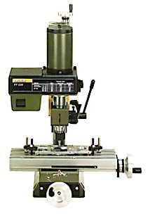
anyone who may have had similar problems. This project is now
completed, the machining of the LCD and main front panels was made very easy by
the use of a Proxxon PF230 Mill/Drill.
The Email sent to P.E magazine is as follows:-
I liked the idea of a LCF meter, especially the L part as this means more
workshop space now that the Marconi Bridge can go. The L parts of the LCF
meter works fine but the C part has a problem in the shape of spurious high
frequency oscillations. The added 68pf referred to in the text file on your
download site stopped the high frequency oscillations but it still started up
in high frequency mode after changing Cx (the unknown capacitor), this
required the meter to be turned off and on again to enable the checking of
another Cx.
From the notes about problems I purchased the HEF version of the 4011, better,
but still needs the 68pf. After checking low and high values of Cx I noticed
value errors, using the correction factor helped but the errors were plus on
low values and minus on high values of
Cx. It seems that the 68pf was changing the frequency from the straight line
at low values of Cx.
I looked at the use of an TL072 op-amp however it would not work at the high
frequency end. Using a 74HC132 for the capacitance
oscillator produced results which were near to actual values for low and high
values of Cx. The note about problems stated that the HCT device could not be
used as a replacement because it would stop the L part of the meter working
properly.
To allow for the different frequency produced by the HC or HCT devices I
adjusted the frequency to the values expected
from the 4011. Thus no modifications are required for the software.
That is:-
4011 f=1/πCR
74HC132 f=1/0.8CR
74HCT132 f=1/0.67CR
Keeping with the 1n capacitor for C and using a larger R makes the meter
work fine at low and high Cx values.
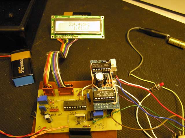
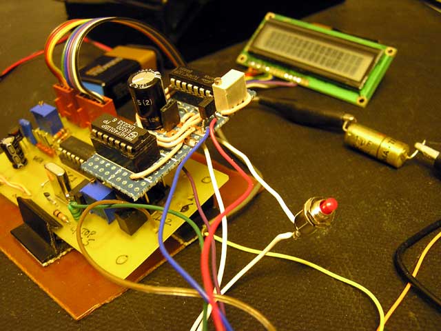
To enable the modifications to be easily implemented I used a long wire wrap
pin socket for IC3 soldered thru a prototype board with the 74HC132 along
side.
The whole assembly then plugs into the original socket for IC3.
Before plugging in the add-on modification unplug IC3 4011 and plug it into
the add-on board. Remove R3, R4 and C7, this will make IC3 pin 5 free to be
used by the add-on board (see schematic). Remove the wires from SW2 pins 2
and 6 and reconnect them to the add-on board.
If the additional 68p capacitor has been fitted then remove it.
Schematic and photo attached.
I hope that this will help any of your readers who have experienced similar
problems.
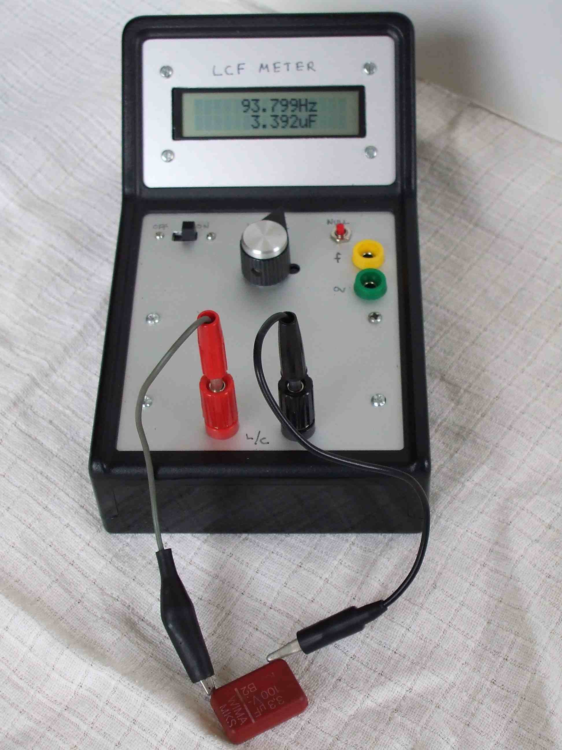
Photographs and schematics
Mike Baker March 2004
The completed meter was housed in a plastic case
already to hand.
Amended August 2006.
---------------------------------------------------------------------------------------------------------------------------